
Troubleshooting Guide for Getinge HS-Series 450 – 15000 GPD RO Systems
We have Expert Technical Knowledge of HS-Series Reverse Osmosis (RO) Systems. That is what you are here for, and it is what we deliver every day
We deliver the benefits of 15 years’ experience in building, programming, testing and repair of all HS-Series RO Systems. We have intimate knowledge of Design, Assembly, Operation and Troubleshooting for Getinge HS-Series Equipment. Look here for news about future upgrades to these systems.
Tech Support - Section 1
Troubleshooting Guide for Getinge HS-Series 450 – 15000 GPD RO Systems
This guide will help you diagnose some of the more common things that can wear out on HS-Series RO Systems, along with the recommended solution or fix. If the answer to the problem is not found here, give us a call. We can help!
|
|
Problem |
Cause |
Recommendation |
|
1. |
Low Production |
a. Membrane has become fouled |
Membrane Replacement (see part number in section 2.1a) |
|
|
|
b. Pre-filters are dirty/clogged |
Pre-filter Replacement (see part number in section 2.1b) |
|
|
|
c. Broken tank bladder |
Tank replacement (see part number in section 2.1c) |
|
|
|
d. Air pressure in tank excessive |
Remove some air from the tank at Schrader valve. |
|
|
|
e. Concentrate valve not set properly |
Perform “startup process” listed in section 2.1e (pg 3) and/or replace membrane (more information in section 2.1e) |
|
|
|
f. Flush solenoid defective |
Replace flush solenoid (1/2” NC Sol # 61301605488. More information in section 2.1f) |
|
|
|
g. Bypass solenoid defective |
Replace bypass solenoid (For 1/2” NO Sol #61301606309) (For 1/2“ NC Sol #61301605488 (More information in section 2.1g) |
|
2. |
Motor Does Not Start |
a. Blown Fuse or Circuit Breaker tripped |
Check Fuses and Breakers. Reset/Replace as needed. |
|
|
|
b. Low inlet water pressure |
Provide water pressure at inlet of at least 50 psi |
|
|
|
c. Float switch has worn out or is stuck open (upper or center) |
Float switch replacement (Part #61301605509) |
|
d. Inlet pressure switch not working (to test connect wires at inlet pressure switch and see if the unit starts up) |
Inlet pressure switch replacement (Part #61301605490) |
||
|
|
|
e. Loose or broken wire at the inlet pressure switch (bad connection) |
Check wire terminals at switch and/or trace wires & repair as needed |
|
|
|
f. Loose or broken wire to float switch (upper or lower) |
Check wire terminals at switch and/or trace wires |
|
|
|
g. Motor contactor worn or burned out |
Replace motor contactor (For PLC Box #61301605947) (For Circuit Board Box #61301605507) (see section 2) |
|
|
|
h. Worn out pump motor |
Pump motor replacement |
|
|
|
i. Blown membrane (glued seems have let go) |
Replace membrane |
|
3. |
Conductivity/TDS too High |
a. Leaky O-ring Seals around the Membrane Permeate Tube |
Replace O-rings in both end-caps (or on both ends of permeate tube on HS-450 membrane) |
|
|
|
b. Bypass solenoid valve stuck open |
Replace bypass solenoid |
|
|
|
c. Bypass pressure switch worn out/broken |
Replace bypass switch |
|
4. |
Unit Starts and Stops repeatedly(short cycles) |
a. Inlet solenoid not opening (electrical) |
Troubleshoot electrical wiring and repair open connection |
|
|
|
b. Inlet solenoid not opening (mechanical) |
Replace inlet solenoid |
|
|
|
c. Inlet pressure switch has loose electrical connection |
Troubleshoot electrical wiring and repair connection |
|
|
|
d. Inlet water flow Inadequate |
Establish adequate inlet water flow (see section 2 for more information) |
|
|
|
e. Tank pressure switch worn or set wrong |
Replace pressure switch |
|
|
|
f. Version of SmartRelay software prior to 110325 |
Update SmartRelay software (call for pricing) |
|
5. |
Unit Does Not Build Pressure |
a. Pump worn or broken |
Replace pump (see section 2 for part number) |
|
|
|
b. Motor wired for 230VAC supply voltage, connected to 115VAC |
Supply correct voltage to the motor, or rewire to correct outlet voltage. |
|
|
|
c. Pump/Motor wired incorrectly making the pump turn the wrong direction |
Wire motor for counterclockwise rotation |
Technical Support - Section 2
1) 1) Low Production, Solution, Part Numbers:
a. Membranes for:
WMHS & HS-450: #61301605535 / HS-1000: #61301605463 / WMHS-1000: #61301605919
HS-2400, 4800, 9600 & 15000: #61301605464
b. Filter Replacement for:
WMHS & HS-450, HS-1000: Sediment Filter– #61301605460 / Carbon Block Filter - #61301605456 / GAC_KDF Filter – #61301605458 (GAC_KDF not used in WMHS RO’s)
WMHS 450 & WMHS-1100 Only: Scale Net Filter - #361073
HS-2400: Sediment Filter - #61301605461 / Carbon Block Filter – #61301605457 / GAC_KDF Filter – #61301605459
HS-4800, 9600, 15000: Sediment Filter - #204036
c. Pressure Tank Replacement for:
WMHS & HS-450 (RO-44): #219007 / WMHS-1100, HS-1000 & 2400 (RO-86): #219010 / HS-4800, 9600, 15000 (RO-119): 219012
d. N/A
e. Concentrate Valve Setup:
i. Open Concentrate Valve 3 complete turns (counter-clockwise).
ii. Close Recirculate Valve fully (until you feel it seat gently)
iii. Begin closing the concentrate valve (watching the permeate float and the feed pressure gauge) until the feed pressure gauge reads 150psi.
iv. Begin opening the Recirculate Valve until the feed pressure drops to, or below 125psi.
v. Watch the Permeate and Concentrate Floats, while you are making these adjustments.
vi. Alternate closing the Concentrate Valve until the feed pressure reaches 150psi and opening the Recirculate Valve until the feed pressure is 125psi until the Permeate Float and the Concentrate Float are even (side by side), at 150psi.
vii. If the pressure cannot be built to 150psi by doing the above procedure, go to #5 on the Tech Support Section 1 Troubleshooting Page and follow the instructions.
f. Flush Solenoid Replacement: All systems 2005 to present have 1/2” Normally Closed Solenoids (NC), Part Number 61301605488. Most HS 4800 – HS 15000 systems prior to 2005 have NC, ¾”FNPT Port size, Flush Solenoid Valves, Part Number 61301605489. Be sure to check the threaded port size before ordering on those systems.
g. Bypass Solenoid Replacement: Check your bypass solenoid before ordering to ensure the correct type is purchased. There are two different variations in service. You can tell which solenoid by checking the first two digits of the serial number on the electrical control box, check the box as described below, or compare to Figure 1.1.
· Circuit board model HS 450 – HS 15000 (used prior to 2005). When you open the electrical box, you will see a circuit board inside; you will need a part number 61301605488.
· SmartRelay model HS 450 – 15000 (2005 - present) compare the bypass solenoid to the flush solenoid mounted on the bottom of the membrane vessel on HS 450 – 2400 and on the back right side of the unit on HS 4800 – HS 15000. If on the bypass solenoid, the part that the green electromagnet is sitting on is taller than the one on the Flush Solenoid, you need part #61301606309. If they are both the same length, you need part number 61301605488 (See Figure 1.1).
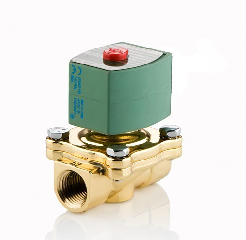 Figure 1.1
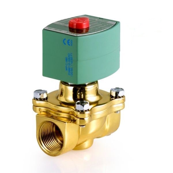
(Normally Closed) #61301605488 (Normally Open) #61301606309
Note: Difference in height between NC and NO versions. The green magnet sits higher on NO version.
2) 2) Motor Not Operational, Solution, Part Numbers
a. Blown Fuse or Circuit Breaker tripped:
i. Check the circuit breaker at the building electrical service panel; reset if tripped.
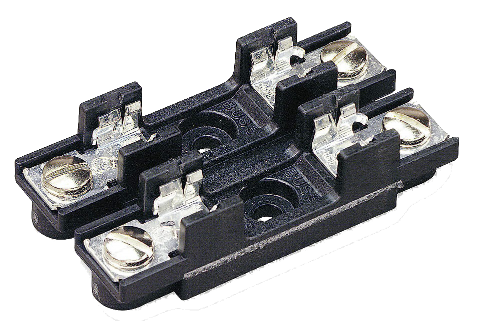
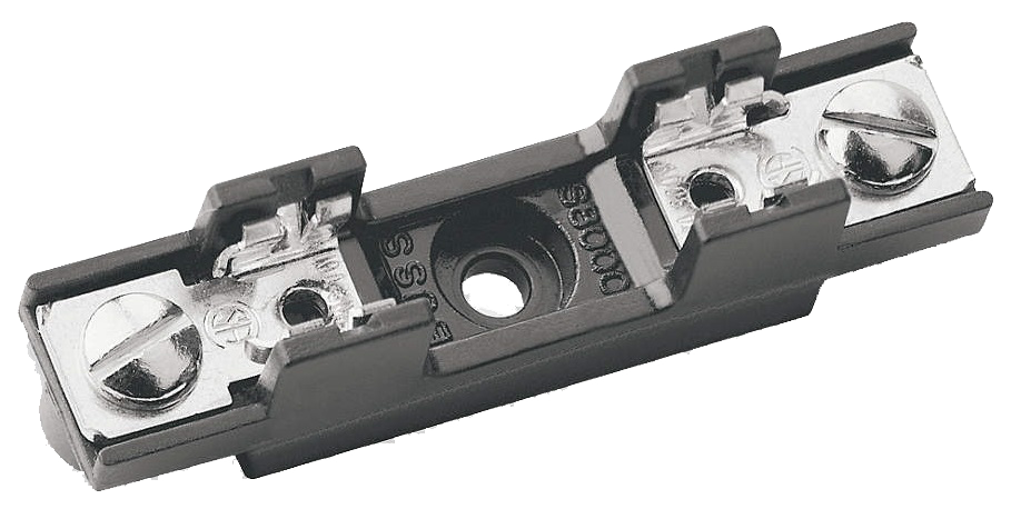
ii. Check the unit fuses and/or circuit breakers. Use an Ohm Meter to test electrical continuity through the fuse shown here in this YouTube Video: https://www.youtube.com/watch?v=1iHRESNMFAg. If the fuse is blown, replace with the correct fuse type. HS 450 – 15000 with SmartRelay Electrical Control Box (see below).
![]()
![]()

![]()
20A Fuse Block: 20A Fuse Part #61301605942 3/4A Fuse Holder: 3/4A Fuse #61301605945
HS 450 – 15000 with circuit board electrical control box (see below).
![]()
![]()
![]()
20/30A Block 20A #61301605502/30A 61301605503 3/4A Fuse Holder 3/4A #61301605945
Circuit Board HS 450 – 2400 take the 20 Amp Fuses and the HS 4800 – 15000 take the 30A Fuses. Replace Fuses if blown.
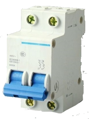
Circuit breakers have replaced the 20A Fuse Blocks on systems built after 2007 and the fuse block can be replaced on the SmartRelay systems built prior to that date (see below). Reset the breaker switches if tripped.
![]()
20A & 32A Circuit Breaker 1A Circuit Breaker
b. Low water pressure at the inlet: This condition to the RO Processor will not allow the low-pressure switch to make contact and thus prevents the motor from starting. To fix the issue, check the incoming water pressure at the point it enters the R.O. System (install a pressure gauge there, if necessary) and verify a minimum of 50psi of static pressure. If below 50psi, you will need to determine the cause and correct the problem. Several things could cause/contribute to the problem:
i. The shut-off valve to the building/room is closed, or partially closed
ii. There could be a blockage in one of the pipes. A blockage could have been caused by recent work on the plumbing; something may have been left inside the pipe when it was sealed shut (a Rag, or piece of paper that was being used to keep foreign objects from entering the pipe, was shoved in too far and forgotten to be removed).
iii. There could be an unknown pressure regulator that is in-line, somewhere before the R.O. Equipment. If a regulator is present, adjust it to 50 – 80 psi (65 psi is a good pressure to set it to).
iv. There is a major water leak elsewhere in the building, which is siphoning off pressure (check for constantly running toilets and sinks). This can be a serious problem, and if you cannot find it quickly, a plumber should be consulted.
v. Pressure from your Municipality or Well, is inadequate. Add an in-line booster pump to feed the equipment water at 50 – 80 psi.
vi. There may be another piece of equipment that is demanding water at the same time as the R.O. System. This condition can cause an intermittent “low pressure situation” that can be hard to diagnose.
c. Leaking O-ring permeate seals: O-ring Seals around the Membrane Permeate Tube (tube that runs down the center of the membrane that sticks out of both ends). HS and WMHS R.O.’s 450 and below have the O-rings attached to the tube. On HS & WMHS Series R.O.’s 1000 and up the O-rings are inside the center of the Membrane Vessel End-Cap’s. Replace the End-Cap O-rings with new ones. Contact us for O-ring Replacement Kit pricing and availability.
d. Inlet pressure switch not working (to test connect wires together at inlet pressure switch and see if the unit starts up). Replace the pressure switch with part number 61301605490. This part number is a kit that contains two brass bushings and the replacement switch. The kit replaces the old style pressure switch shown below:
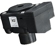
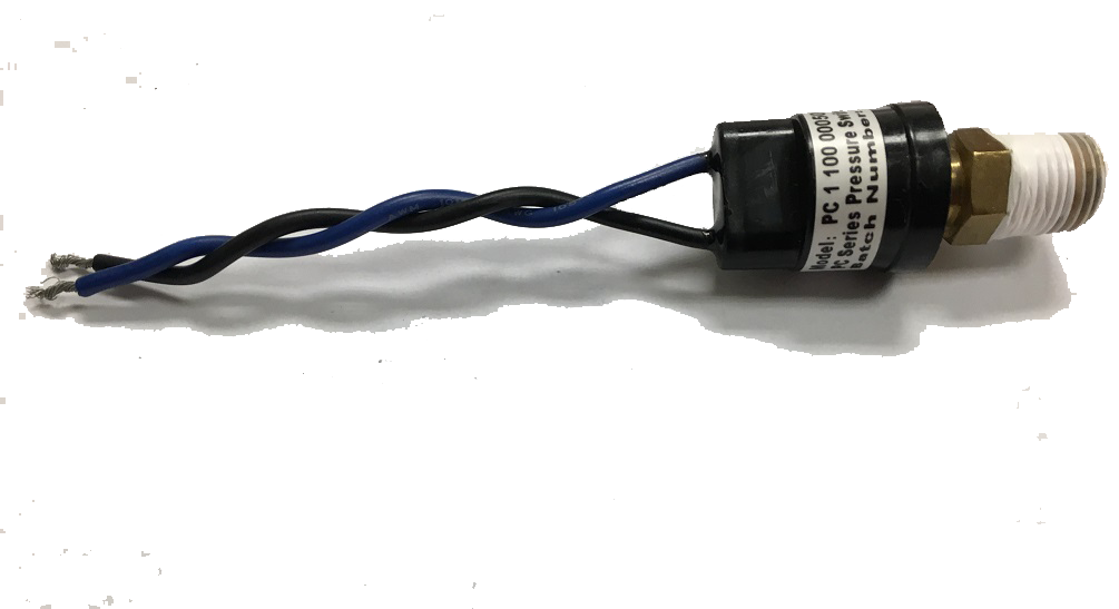
Old Style Pressure Switch New Style Pressure Switch
e. Loose or broken wire Inlet Pressure Switch (bad connection): There is a loose or broken wire at the inlet pressure switch, or where the wires connect into the SmartRelay. Due to vibration, or accident, the wires can be “stressed” to the point that they are no longer making adequate contact resulting in an “open circuit” condition. Replace the wire or connector to repair the open circuit.
3) 3) Conductivity/TDS too High, Solution, Part Numbers:
a. Membrane Blown: Membrane glued seams have let go, usually due to excessive pressure and/or feed water temperature in excess of 100°F (37.8°C). Replace the blown membrane with a new one (see section 2.1a for part numbers).
b. The Bypass Solenoid Valve is stuck in the open position: The bypass solenoid can be replaced, or in some cases rebuilt (if you are not highly familiar with solenoid diagnostics and repair, it is best to replace it). To test the solenoid, with the tank full unplug the RO System from the wall socket. For correct part numbers for solenoid replacement see section 2.1g.
c. Bypass Pressure Switch/Float worn out/broken: The Bypass Pressure Switch, or Bypass Float is stuck open forcing the Bypass Solenoid in the open position. This allows the “Tap” water to mix with Reverse Osmosis water going to the equipment effectively raising the total dissolved solids level and thus negating the purpose of the RO System. Replace the Bypass Switch, or Float. Bypass Pressure Switch Part Number #61301605490. Bypass Float Part Number #61301605509.
4) 4) RO Processor Starts and Stops repeatedly(short cycles)
a. The Inlet Solenoid is not opening (electrical): If the wires become stressed, due to vibration and/or the wire being pulled too tightly, the wire can become loose and not make adequate contact with the crimped female spade connector. There could also be a damaged segment of wire. Check the outer insulation of the wire to make sure there is no damage. Also, check the end of the wire that is inserted into the SmartRelay Output Q1-2, to make sure it is inserted all the way in the socket and tightened properly. Troubleshoot the electrical wiring and repair any open connection.
b. The Inlet Solenoid is not opening (mechanical): Rebuild (only if you are proficient with diagnosing and repairing solenoid valves), or replace the Inlet Solenoid. HS or WMHS 450 – 2400 part number 61301605488. HS 4800 – 15000 part number 234085. Some HS 4800 – 15000 systems prior to 2008 have plastic Inlet Solenoid Valves. If they fail, the valves should be replaced with a brass valve (part number listed above. The plastic valve is no longer available). Replacing the valve with a brass version may require some minor modification/replacement of the PVC piping connecting it to the rest of the RO System. Most likely, you will be able to cut a piece out of the upper pipe and use a 1” PVC Coupler to reconnect the shortened pipe, so that it fits correctly into the bulkhead fitting.
c. Inlet pressure switch has loose electrical connection: If the wires become stressed, due to vibration and/or the wire being pulled too tightly, the wire can become loose and not make adequate contact with the crimped male and female spade connectors. There could also be a damaged segment of wire. Check the outer insulation of the wire to make sure there is no damage. In addition, check the end of the wire that is inserted into SmartRelay Input “i4”, to make sure it is inserted all the way in the socket and tightened properly. Troubleshoot the electrical wiring and repair any open connection.
d. Inlet water flow is not adequate (RO System starving for water): The pipe size delivering water to system inlet is not adequate to keep it running. Usually in this situation, the R.O. System is using the pipe delivering water as a straw. It is actually sucking the water out of it. What happens is that the static pressure is e.g. 60psi, until the unit starts. As soon as the system starts the pressure drops below the pressure switch shut-off limit (the unit is now sucking water out of the line), and it shuts down immediately, then restarts within 90 seconds when the static pressure is reestablished. The on/off cycle repeats indefinitely, until the problem is addressed. There is a ways of cheating this condition, but it should only be a short-term solution. The low pressure switch can be disconnected and the 2 wires connected together for a short period of time. Doing so would void the pump/motor warranty though, so it used only as a last resort, while the low flow situation is being corrected. The system needs to be closely monitored during this period, to ensure that the System does in fact have enough water going to it, to be able to operate. The pressure cannot be allowed to go below 3psi, because there is no safety device to protect the pump/motor without the low-pressure switch being engaged.
Warning: Do not run the HS Series RO unsupervised, with the low-pressure switch jumped.
e. Tank pressure switch worn or set wrong: The Tank Pressure Switch is difficult to set if the smaller setscrew is moved. The smaller screw changes the size of the hysteresis, however adjusting it will change the upper pressure limit as well. The Hysteresis is set at 20psi at the factory. It is best to never touch the smaller screw if you need to make adjustments to the switch. The switch is mechanical so it will wear out eventually. You can try to set it using the center setscrew. Clockwise to increase the on/off pressure and counterclockwise to reduce the on/off pressure. If the switch is not activating to allow the RO system to restart when the tank pressure drops below 40psi, it is generally time to replace the switch. Part number 61301605491.
f. Version of SmartRelay software prior to version 110325: From time to time there have been releases of updates to the software for the control system SmartRelay. The software released after 2011 is able to handle low flow situations better than previous versions, and can help keep your system from short cycling. If you have a version prior to 110325, you can order that upgraded version from us. The next generation of SmartRelay that we will offer, will have remote monitoring capabilities. Check the version of SmartRelay, to see if it is capable of receiving the upgraded software. If the SmartRelay model is FL1C-H12RCA, it will need to be replaced with a FL1E-H12RCA to accept the new software.
The SmartRelay part number is: 61301605949.
5) 5) Unit Will Not Build Pressure
a. Pump worn or broken:
i. The HS & WMHS 450 – 2400 use a carbon vane pump, which wears out over time and with use. As the “Vanes” (kind of like paddles), rotate within the pump body they begin to wear down leaving gaps between the Vane and the body. As the gaps get larger, more and more water is able to escape, thus less pressure is available to force water through the membrane. Replace the pump.
1. WMHS & HS-450 pump part number 61301605527
2. WMHS & HS-1000/1100 pump part number 61301605493
3. HS-2400 pump part number 61301605494
ii. The HS-4800 – HS-15000 use a large vertical pump and motor combination that is very complex. The pump has several “stages” that each acts as its own separate pump. Each stage pumps the water to a higher pressure ten hands it off to the next stage, which take it to a higher pressure. The pump is made of stainless steel internally and is very rugged and will have a very long life, however they do have parts that wear out over time. If you have experience with these Pump/Motor combinations, the pump portion can be replaced separate from the motor portion. It is important if you are going to separate the motor and pump, that you use the pump head spacer to ensure that the motor shaft is inserted at the proper level. If the spacer is not used, the shaft will not engage properly and it will shear off inside the pump ruining it. We therefore recommend that the pump/motor be replaced as a unit.
1. HS-4800 – 9600 Pump/Motor part number 61301605500
2. HS-15000 Pump/Motor part number 61301605501
b. Motor wired for 230VAC supply voltage, connected to 115VAC: This problem is usually confined to the smaller motors on the WMHS & HS-450 – 2400. It usually occurs when the motor is replaced in the field and the technician wires it up according to the schematic on the side of the motor, but inadvertently connects them in the 230V configuration. When the motor is started it rotates very slowly and will not build any appreciable pressure. The solution is to simply rewire to the correct voltage and restart the RO System. If the scenario is reversed and the unit is wired for 115V and plugged into 230 source voltage, there is a very good chance the motor will begin to smoke right away and it will be ruined.
Caution: Running the motor in either configuration will result in severe damage to the motor if it is allowed to run for a period of more than a minute.
c. Pump/Motor wired incorrectly making the pump turn the wrong direction: This problem usually occurs in the larger systems with 2HP and 3HP Motors. It happens when a technician replaces a motor in the field and wires it according to the wiring diagram on the side of the motor instead of the one located inside the electrical control box door. These motors must be wired for reverse rotation in order for the pump to turn the proper direction and build significant pressure. The system will run, and build some pressure turning backwards, so do not be fooled. You will not be able to get the system to produce the 100psi that is required for proper operation. Always ensure that you have wired the motor to turn in reverse (counterclockwise) rotation and that the shaft is turning in the direction of the arrows on the cast iron pump motor cradle. You can temporarily remove the chrome covers to observe the rotation. Shut the processor off and replace cover immediately, once the shaft has stopped moving.
Caution: Do not get any part of your body close to the shaft while it is turning with the cover removed. Serious injury can occur.